Latest version , Free shipping DIY Kits ATU-100 1.8-50MHz ATU-100mini Automatic Antenna Tuner by N7DDC 7×7 With firmware – 509
Original price was: 100,50 $.34,66 $Current price is: 34,66 $.
Buy Latest version , Free shipping DIY Kits ATU-100 1.8-50MHz ATU-100mini Automatic Antenna Tuner by N7DDC 7×7 With firmware at for . Find more 509, 5092101 and products. Enjoy ✓Free Shipping Worldwide! ✓Limited Time Sale ✓Easy Return.

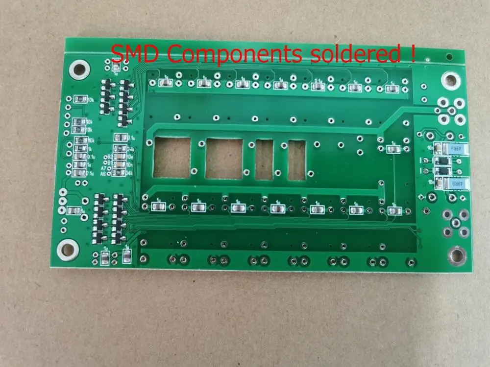
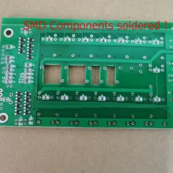
NOTE :
1.DIY kit, need to have welding ability;
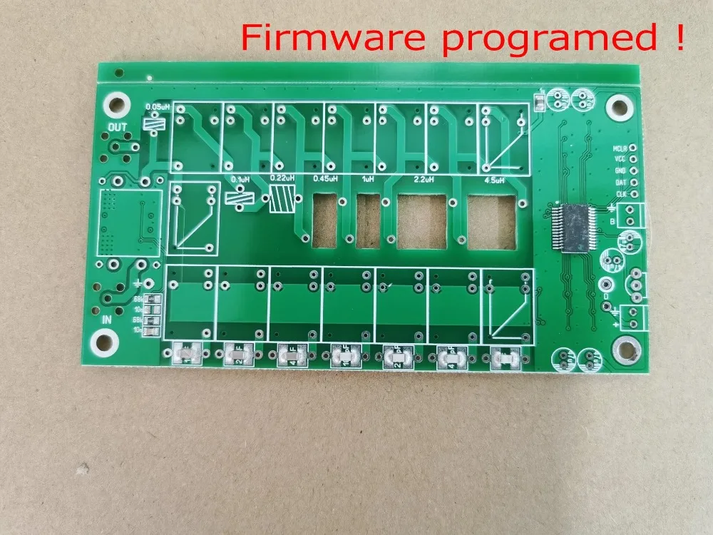
2. firmware has been programmed, for the 1602 LCD
3.SMD electronic components have been soldered,
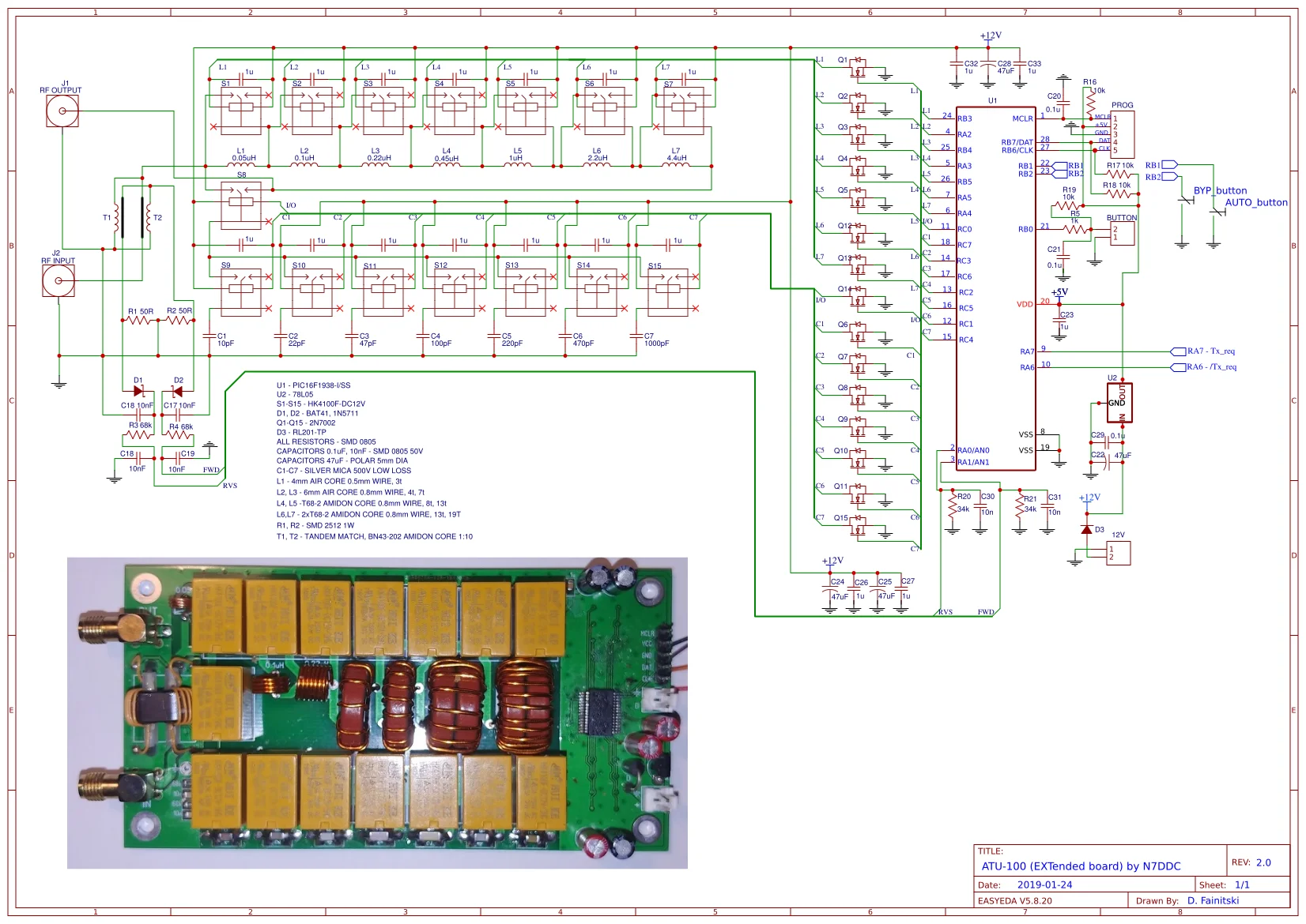
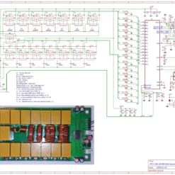
4.Circuit schematic and firmware, please contact us.
5. PIC chip soldered on the board
KIT of ATU (Automatic Antenna Tuner) developed by N7DDC
All information about project you can find on GitHub (N7DDC).
Power supply range: 10 – 15 VDC
Max current : 450mA
Max working power: 100 watts
Max measured power: 150 watts
Minimum power for tuning start: 1 watt
Recommended maximum power while tuning not above 30 watts. (after tuning you can set 100 watts and work on this power)
Minimum measured power: 0.1 watt
Step for measurement on powers under 10 watts: 0.1 watt
Step for measurement on powers above 10 watts : 1 watt
Power measurement accuracy : 10%
Maximum inductance set: 8.5 uH
Minimal step for setting inductance: 0.1 uH
Maximum installed capacity: 1870 pF
Minimal step for setting capacity: 10 pF
100 Watts tuner, 7×7 (7 capacitors x 7 coils) based on PIC 16F1938.
Dimentsion – 120 mm x 62 mm.
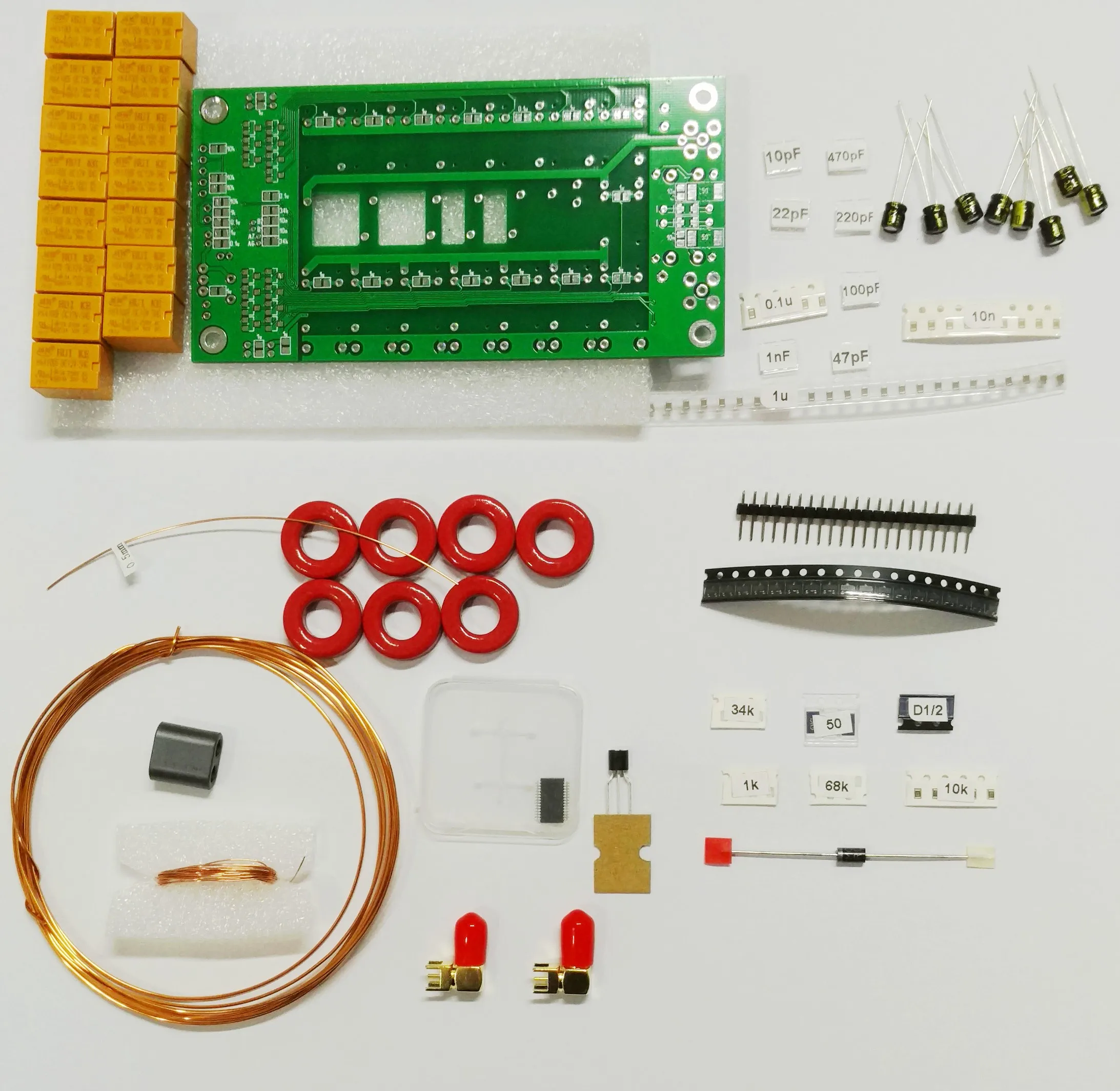
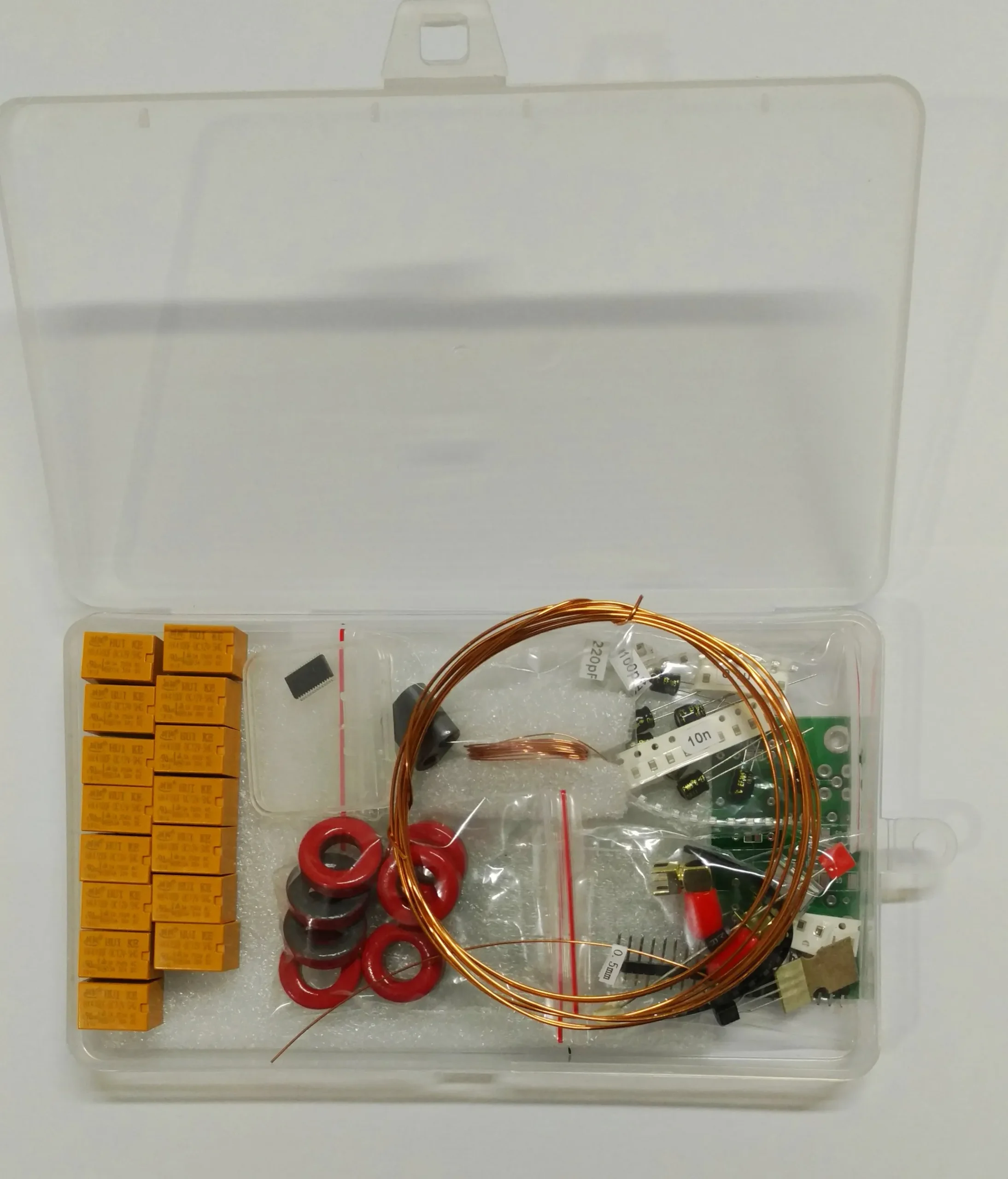
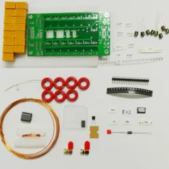
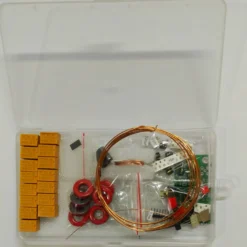
KIT included:
PCB for ATU-100 7×7 HF autotuner
+ set of toroids:
– T68-2 (6pcs);
– BN43-202 (1pcs).
+ set of parts:
– PIC16F1938 (1pcs) soldered on PCB with default firmware v3.0
– 100R 2512 1% (4pcs).
– relay HK4100F-DC12V (15pcs)


window.adminAccountId=231173057;
| value | not defined |
|---|
Be the first to review “Latest version , Free shipping DIY Kits ATU-100 1.8-50MHz ATU-100mini Automatic Antenna Tuner by N7DDC 7×7 With firmware – 509”
Related products


Reviews
There are no reviews yet.