

AXT600 UA874 Antenna Distribution System With Spectrum ManagementRF Signal Splitter For Wireless Mic Signal Booster AMP –
Original price was: 452,40 $.156,00 $Current price is: 156,00 $.
Buy AXT600 UA874 Antenna Distribution System With Spectrum ManagementRF Signal Splitter For Wireless Mic Signal Booster AMP at for . Find more , and products. Enjoy ✓Free Shipping Worldwide! ✓Limited Time Sale ✓Easy Return.

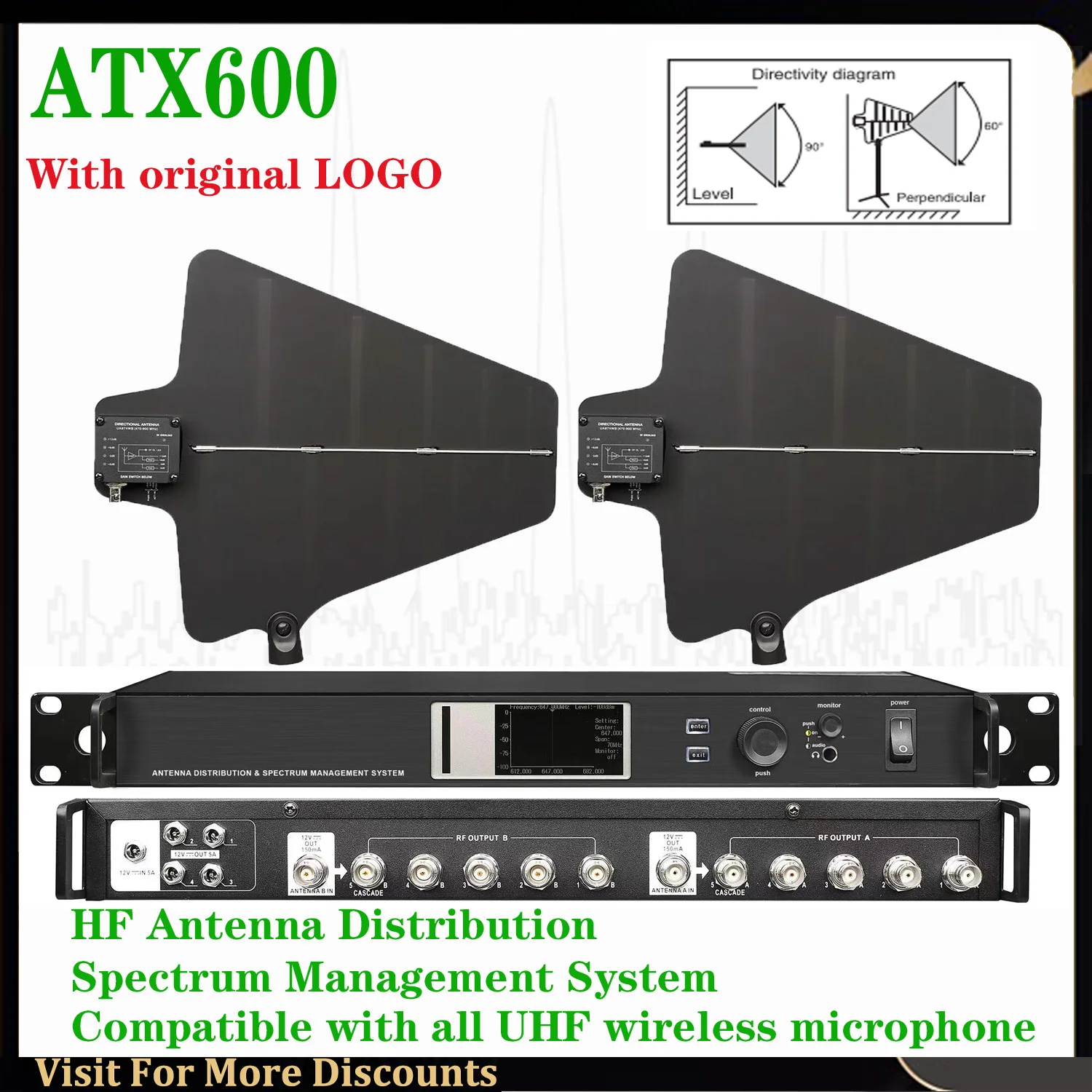
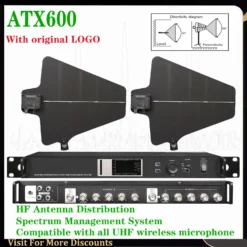
AXT600 UA874 Antenna Distribution System With Spectrum ManagementRF Signal Splitter For Wireless Mic Signal Booster AMP 470-952MHz
SYSTEM FUNCTION:
1.Compatible with all major brands and used by all UHF band wireless microphone receivers.
2.The on-site radio spectrum scanning and detection function provides a basis for the allocation and management of radio frequency points.
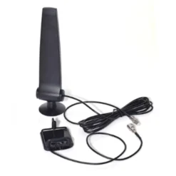
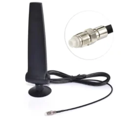
3.Directional omnidirectional, wall-mounted and other antennas with different types and performances are available.
4.High-frequency signal band-pass filtering function, filtering signals outside the bandwidth to cause interference to the system.
5.High-performance materials and circuits are used to ensure maximum signal sensitivity and port crosstalk isolation, and can provide stable radio signals for many wireless receivers.
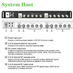
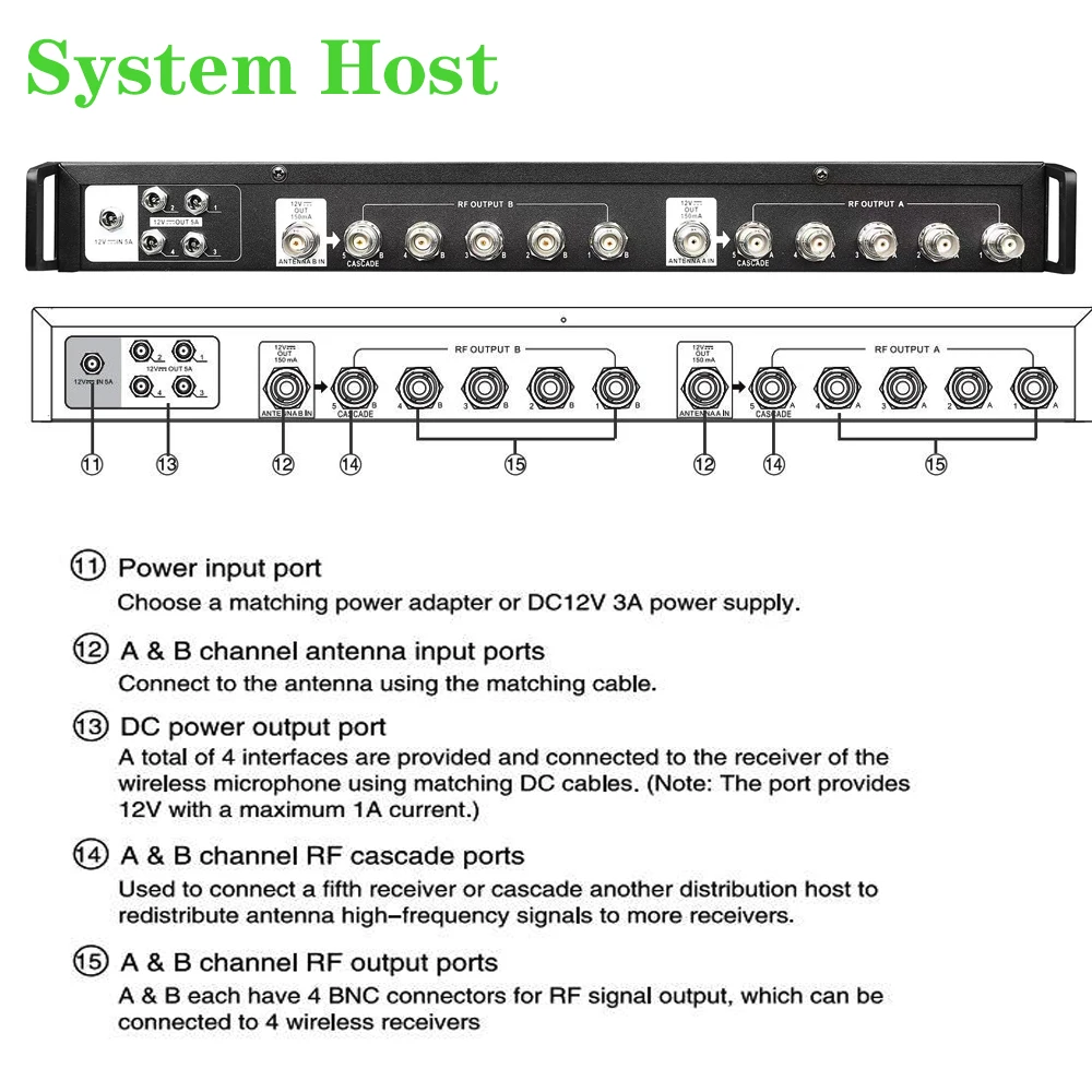
6.Two 50ohms BNC antenna cascade ports can connect an additional distribution host or a fifth wireless receiver.Each
distribution host provides 4 channels of DC12V/1A power output power supply capacity. The package includes the support hardware
and high-frequency connection cable required for installing the antenna.
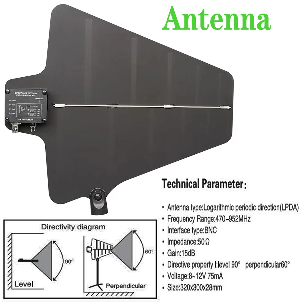
Technical Parameter 1:
Antenna type:Logarithmic periodic direction(LPDA)
Frequency Range:470-952MHz
Interface type:BNC
Impedance:50OHMS
Gain:15dB
Directive property l:level 90°perpendicular 60°
Voltage:8~12V 75mA
Size:320x300x28mm
Technical Parameter 2
RF band—470-952MHz
Third-order filtering —24dBm intersection slope
Gain —–(Distribution port 1dB)(Cascade port 0dB)
Impedance—50OHMS
RF port— BNC
Antenna feed—12V 150mA
Power input— DC +12V 1A
Power output——–4-port maximum DC+12V1A
Distributor size—482x44x200MM
Working temperature-(-20° -+50°)


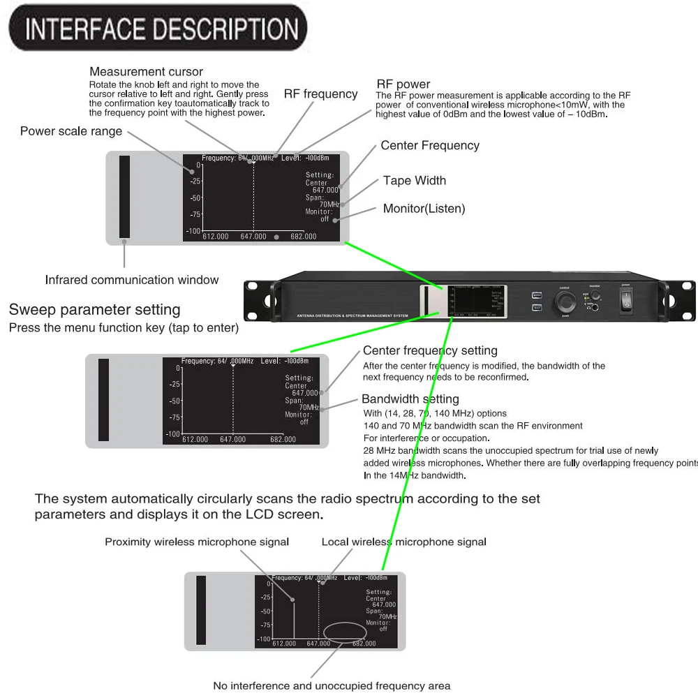
Spectrum scanning
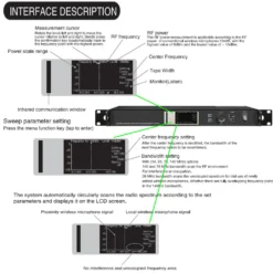
Set the center frequency of the spectrum scanner, and conduct a scan with a bandwidth of 70MHZ at the lowest and the highest frequency of the wireless microphone used.Ater that, the center frequency of the scanner and the center frequency of the wireless microphone should be selected at 28MHz for scanning.
Pay attention to observe the changes when closing and opening other equipment in the cabinet, such as stage lighting and LED wall. If you see that the curent interface changes very little, it proves that the antenna is placed properly and other equioment does not produce radio freauencyinterterence. If there are adjacent frequency point signals in the interface, t is possible to find the cross-freuency phenomenon.the frequency point is newly arranged, it is necessary to avoid conflict with these signals and select the area without interference and not occupied.
After the wireless microphone frequency is selected, set the center frequency of the scanner to the same, because the RF spectrum is dynamic and complex, which is convenient for observation.For
example, sweep-frequency interference signals may occur during motor startup or electric welding.When these mobile interference can not be eliminated, the position and direction of the antenna should be re-selected and placed.


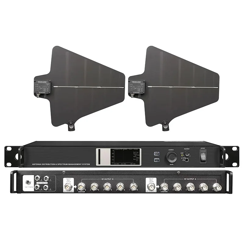
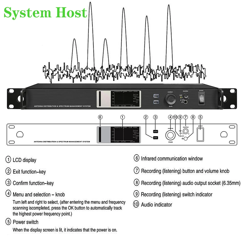
BRIEF DESCRIPTION:
The UHF antenna distribution and spectrum management system is com-posed of a frequency sweep spectrometer system
designed for the special frequency band of wireless microphone and a RF signal amplification and distribution system with dual antenna signal receiving circuit. The RF scanning svstem uses a LCD monitoring interface. Through scanning, it can find various existing signals such as similar wireless microphones in similar frequency bands, noise emitted by LED walls, radio and television stations, wireless telephone base station signals and so on.Therefore, it can help to select the frequencies that are not occupied for the use of new wireless microphones.
The RF antenna amplification and distribution system has the function of filtering. The signal in the passband passes through with low loss.The interference signal outside the passband is filtered and attenuated. The filtered useful RF signal is amplified and divided into multiple outputs to compensate for insertion loss The distribution system allows four receivers to use, and is also equipped with a power plug that supplies power to each receiver. In addition, it is also equipped with a RF signal cascade port that can be connected to the antenna input port of the fifth receiver or the second set of antenna distribution system. Generally, when the RF signal is divided into multiple outputs, the signal will be attenuated. The system can amplify and compensate the signal to ensure that it provides a strong signal for the receiver.
APPLICATION SKILLS OF THE BEST EFFICIENCY OF THE SYSTEM
Antenna placement:
1.When fixing the antenna, pay attention to the following:
2.The antenna and receiver must use the same frequency band.
3.Install the antenna at a distance of one wave length (two feet).
4.Adijust the antenna position so that the transmiter is free of any obstacles (including spectators) within the sight range.
5.Keep the antenna awav from metal objects.
Cable maintenance:
Install the antenna at a distance of one wave length (two feet).
1.Avoid cable angle bending or twisting.
2.Minimum bending radius 3CM Do not use temporary clamps (such as fixing cables with nails)
3.Bending changes the shape of the cable
4.Do not use it for outdoor installation in the sun and rain
5.Do not expose to extremely high humidity.
Other associations:
1.The wireless microphone should use high-efficient alkaline battery, and avoid using ordinary carbon battery.
2.The wireless receiver shall be placed within the visual range of the transmitter and free of obstructions.
3.Wireless microphones should not be used in places with electromaanetic radio freauency interference.
4.The transmitting antenna of the wireless handheld microphone is built into the bottom of the microphone.Avoid holding
the bottom of the microphone when using it, otherwise the transmitting efficiency will be reduced.
5.The antenna should not be placed in places exposed to the sun and rain. lt should not be placed on the ground or on
the wall. It should be placed at a height of 1.6 meters above the ground.
System Components:
1.Antenna -2pcs
2.Antenna mounting bracket —2pcs
(Assembly parts, to be purchased separately)
3.Signal gainer –2pcs
(Assembly parts, to be purchased separately)
4.System host—1pcs
5.External power adapter—1pcs
6.RF signal line 0.5m —10pcs
7.RF signal line 3.2m—2pcs
(Optional with other lengths)
8.DC power supply line —4pcs
9.Instruction manual—1pcs
window.adminAccountId=245214424;
| Color | Antenna only UA874, Full set, ATX600 Distribution |
|---|
5 reviews for AXT600 UA874 Antenna Distribution System With Spectrum ManagementRF Signal Splitter For Wireless Mic Signal Booster AMP –
Add a review
Related products


Gianmaria De Sario –
The item got stuck in customs, probably missing.
However, the seller did endeavor to unblock the situation and eventually reimbursed me the cost.
Honest
Wendi Raver –
As described
Micael Montes –
Excellent Product!!
Aliya Fernandez –
Craig Piro –